![]() The newly published 2021 IBC and IRC codes include some important advancements to water vapor retarder provisions. These relate to properly coordinating the use of cavity and continuous insulation materials used for energy code compliance with water vapor retarders used to comply with the building code. A typical wall assembly of this type is shown in Figure 1. This process of coordination is made easy with wood- and steel-frame wall calculators.
The newly published 2021 IBC and IRC codes include some important advancements to water vapor retarder provisions. These relate to properly coordinating the use of cavity and continuous insulation materials used for energy code compliance with water vapor retarders used to comply with the building code. A typical wall assembly of this type is shown in Figure 1. This process of coordination is made easy with wood- and steel-frame wall calculators.
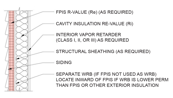
Figure 1. Typical Cavity + Continuous Insulation Wall Assembly.
Figure 2 shows the new 2021 IRC code language for vapor retarders. The 2021 IBC code language will be similar (except [as noted]). While this may appear to be a lot to digest, it is actually fairly straightforward and effective. To help, the most significant aspects of the new provisions in Figure 2 can be summarized as follows:
- A new format uses look-up tables to make it easier to identify all prescriptive requirements applicable to a given climate zone for a given frame wall assembly. For example, Table R702.7(2) is the launching point for determining water vapor retarder requirements and options. Other tables and text provide details for specific conditions of use.
- New provisions are provided for use of foam plastic insulating sheathing (continuous insulation) in combination with a Class II vapor retarder such as coated Kraft paper facers on fiberglass batt cavity insulation. See footnote ‘c’ in Table R702.7(2), which points to specific requirements in Table R702.7(4). This table compliments existing provisions for use of Class III vapor retarders while maintaining adequate inward drying potential and promoting better alignment with energy code R-value requirements for continuous insulation.
- In the 2021 IBC, the Class III vapor retarder provisions in Table R702.7(3) are expanded to apply to all of Climate Zone 4, not just Marine 4 as the 2021 IRC maintains. Table R702.7(2) also clarifies that Class III vapor retarders are permissible in Climate Zones 1-3 with no special requirements.
- The Class III vapor retarder provisions in Climate Zones 7 and 8 are differentiated and strengthened to address an inadvertent error in prior codes that treated Climate Zones 7 and 8 the same.
- In footnote ‘b’ of Table R702.7(2), the code specifically addressed the avoidance of so-called “double vapor barrier” walls (i.e., having Class I vapor retarder materials on both sides of the assembly). These types of walls have performed well in some conditions of use, such as cold-dry climates with use of appropriate weather protection and application of sufficient exterior continuous insulation. However, there also are many cases where they have not performed well, such as moist climates coupled with poor weather protection practices and inappropriate use of interior vapor barrier in warm-humid climates. One way, however, to realize the winter vapor control benefits of a Class I interior vapor retarder while avoiding the low inward drying potential problem of a double vapor barrier is addressed in item 6 below.
- The code now recognizes “smart” or responsive vapor retarders for use in any climate zone as shown in footnote ‘a’ of Table R702.7(2). The code defines a responsive vapor retarder as any Class I or II vapor retarder (based on dry-cup water vapor permeance) that also has a water vapor permeance of greater than 1 perm (based on wet-cup water vapor permeance). When used on the interior side as a vapor retarder, they promote inward drying by “opening up” in periods or seasons where inward vapor drives occur (most prominently during spring and summer months). In the winter, they “close up” to restrict water vapor from moving into the assembly when outward vapor drives are the strongest and most persistent.
R702.7 Vapor Retarders. Vapor retarder materials shall be classified in accordance with Table R702.7(1). A vapor retarder shall be provided on the interior side of frame walls of the class indicated in Table R702.7(2), including compliance with Table R702.7(3) or Table R702.7(4) where applicable. An approved design using accepted engineering practice for hygrothermal analysis shall be an alternative. The climate zone shall be determined in accordance with Section N1101.7 (R301.1).
Exceptions:
- Basement walls.
- Below-grade portion of any wall.
- Construction where accumulation, condensation or freezing of moisture will not damage the materials.
- A vapor retarder shall not be required in Climate Zones 1, 2, and 3. [This exception is not in 2021 IBC]
R702.7.1 Spray foam plastic insulation for moisture control with Class II and III vapor retarders. For purposes of compliance with Tables R702.7(3) and R702.7(4), spray foam with a maximum permeance of 1.5 perms at the installed thickness applied to the interior side of wood structural panels, fiberboard, insulating sheathing or gypsum shall be deemed to meet the continuous insulation moisture control requirement in accordance with one of the following conditions:
- The spray foam R-value is equal to or greater than the specified continuous insulation R-value.
- The combined R-value of the spray foam and continuous insulation is equal to or greater than the specified continuous insulation R-value.
TABLE R702.7(1)
|
|
|
CLASS |
ACCEPTABLE MATERIALS |
|
I |
Sheet polyethylene, nonperforated aluminum foil, or other approved materials with a perm rating of less than or equal to 0.1. |
|
II |
Kraft-faced fiberglass batts, vapor retarder paint, or other approved materials applied in accordance with the manufacturer’s installation instructions for a perm rating greater than 0.1 and less than or equal to 1.0. |
|
III |
Latex pain, enamel paint, or other approved materials applied in accordance with the manufacturer’s installation instructions for a perm rating of greater than 1.0 and less than or equal to 10.0. |
TABLE R702.7(2)
|
|||
|
CLIMATE ZONE |
VAPOR RETARDER CLASS |
||
|
CLASS Ia |
CLASS IIa |
CLASS III |
|
|
1, 2 |
Not Permitted |
Not Permitted |
Permitted |
|
3, 4 [except Marine 4] |
Not Permitted |
Permittedc |
Permitted |
|
Marine 4, 5, 6, 7, 8 |
Permittedb |
Permittedc |
See Table R702.7(3) |
- Class I and II vapor retarders with vapor permeance greater than 1 perm when measured by ASTM E96 water method (Procedure B) shall be allowed on the interior side of any frame wall in all climate zones.
- Use of a Class I interior vapor retarder in frame walls with a Class I vapor retarder on the exterior side shall require an approved design.
- Where a Class II vapor retarder is used in combination with foam plastic insulating sheathing installed as continuous insulation on the exterior side of frame walls, the continuous insulation shall comply with Table R702.7(4) and the Class II vapor retarder shall have a vapor permeance of greater than 1 perm when measured by ASTM E96 water method (Procedure B). (NOTE: This requires that the Class II vapor retarder is also a “smart” or responsive vapor retarder, like coated Kraft paper facer on fiberglass batts; use of a Class I responsive vapor retarder would provide equal or better performance.)
TABLE R702.7(3)
|
|
|
CLIMATE ZONE |
CLASS III VAPOR RETARDERS PERMITTED FOR:a,b |
|
Marine 4 [2021 IBC includes all of Zone 4] |
Vented cladding over wood structural panels. |
|
Vented cladding over fiberboard. |
|
|
Vented cladding over gypsum. |
|
|
Continuous insulation with R-value ≥ 2.5 over 2 x 4 wall. |
|
|
Continuous insulation with R-value ≥ 3.75 over 2 x 6 wall. |
|
|
5 |
Vented cladding over wood structural panels. |
|
Vented cladding over fiberboard. |
|
|
Vented cladding over gypsum. |
|
|
Continuous insulation with R-value ≥ 5 over 2 x 4 wall. |
|
|
Continuous insulation with R-value ≥ 7.5 over 2 x 6 wall. |
|
|
6 |
Vented cladding over fiberboard. |
|
Vented cladding over gypsum. |
|
|
Continuous insulation with R-value ≥ 7.5 over 2 x 4 wall. |
|
|
Continuous insulation with R-value ≥ 11.25 over 2 x 6 wall. |
|
|
7 |
Continuous insulation with R-value ≥ 10 over 2 x 4 wall. |
|
Continuous insulation with R-value ≥ 15 over 2 x 6 wall. |
|
|
8 |
Continuous insulation with R-value ≥ 12.5 over 2 x 4 wall. |
|
Continuous insulation with R-value ≥ 20 over 2 x 6 wall. |
|
- Vented cladding shall include vinyl, polypropylene, or horizontal aluminum siding, or brick veneer with a clear airspace as specified in Table R703.8.4(1), or other approved vented claddings.
- The requirements of this table apply only to insulation used to control moisture in order to permit the use of Class III vapor retarders. The insulation materials used to satisfy this option also contribute to but do not supersede the thermal envelope requirements of Chapter 11.
TABLE R702.7(4)
|
|
|
CLIMATE ZONE |
CLASS II VAPOR RETARDERS PERMITTED FOR:a |
|
3 |
Continuous insulation with R-value ≥ 2. |
|
4, 5, and 6 |
Continuous insulation with R-value ≥ 3 over 2 x 4 wall. |
|
Continuous insulation with R-value ≥ 5 over 2 x 6 wall. |
|
|
7 |
Continuous insulation with R-value ≥ 5 over 2 x 4 wall. |
|
Continuous insulation with R-value ≥ 7.5 over 2 x 6 wall. |
|
|
8 |
Continuous insulation with R-value ≥ 7.5 over 2 x 4 wall. |
|
Continuous insulation with R-value ≥ 10 over 2 x 6 wall. |
|
- The requirements of this table apply only to insulation used to control moisture in order to permit the use of Class II vapor retarders. The insulation materials used to satisfy this option also contribute to but do not supersede the thermal envelope requirements of Chapter 11.
Figure 2. New Vapor Retarder Provisions for the 2021 I-Codes (IRC shown with key IBC differences [noted])
NOTE: For more options and an automated means of compliance, refer to ABTG Research Report No. 1701-01 and these wall calculators.
One significant consideration still missing from the IRC and IBC water vapor retarder provisions is that the code lacks a means of controlling the vapor permeance on the interior and exterior side of wall assemblies that do not include continuous insulation to control water vapor. For example, the code provisions in Figure 2 for walls with continuous insulation (see Figure 1) rely on compliance with underlying “insulation ratios,” which vary by climate, to ensure the inside of the wall stays warm and avoids the dew-point temperature or high humidity levels. For walls without continuous insulation (see Figure 3), the ratio of permeance of outer and inner layers of the wall must be controlled in a similar manner by use of permeance ratios that also should vary with climate. However, such a methodology remains absent from the code.
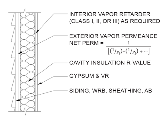
Figure 3. Typical Cavity Insulation Only Wall Assembly.
For additional information and design guidance on the topics addressed in this article, refer to ABTG RR No. 1701-01, and the wall calculators that evaluate and implement insulation ratios and permeance ratios as applicable for walls with cavity insulation only, cavity and continuous insulation, or just continuous insulation.