Executive Summary
This article provides an analysis of three equivalent wall assemblies from a thermal performance perspective that have very different insulation R-value specifications: R-20 + 0ci, R-13 + 5ci, and R-0 + 15ci. All three satisfy the U-factor requirement in the IECC, though only the first two are mentioned specifically in the prescriptive method table. The goal of this article is to open the door to considering wall assembly innovation via greater u-factor calculation knowledge. To make the engineering easier we have also provided a link to a wall calculator developed by the Applied Building Technology Group.
In our last article, we discussed the math behind the prescriptive R-value requirements for walls found in the building codes. Those who are familiar with the energy codes know this is only half the story. In codes such as 2015 IECC and 2010 ASHRAE 90.1, there is a table listing u-factor requirements in addition to the table listing R-value requirements. This immediately raises several questions:
- Why are there two paths to compliance?
- Is one path easier to satisfy than the other?
- Do I need to fulfill both requirements in order to satisfy the code?
In this article, we will address these questions, and attempt to clear up any remaining confusion.
To start, let’s review some of the terms. When we discuss the u-factor (or C-factor) of a component or an assembly, we are describing its thermal conductance. A u-factor is given in units as Btu/(°F·ft2·h). One way of understanding these units is the rate of heat transfer (Btu/h) through a material with a given u-factor is proportional to the temperature difference on either side of the material (°F) and the surface area available (ft2).
On the other hand, when we discuss the R-value of a material or assembly, it describes its thermal resistivity, or resistance to heat flow. In the United States, the units for R-value are simply the inverse of the u-factor and so the units are °F·ft2·h/Btu. It follows then that good conductors have low R-values and high u-factors and good insulators have high R-values and low u-factors. If you know the R-value of a layer or an assembly, you can find its u-factor by simply calculating the inverse.
A note on terminology: while any layer of material can be described by its R-value, U.S. energy codes only refer to the R-values of insulation layers in the prescriptive R-value compliance path. Conversely, while any layer or assembly also has a u-factor, the energy codes only discuss the u-factors of entire wall assemblies. When this is done, a capital ‘U’ is used. For the remainder of this article we will use a capital ‘U’ when discussing complete assembly U-factors.
At this point, our initial problem might seem even more confusing than it did initially. If an R-value and a u-factor are just two sides of the same coin, why would the energy codes include both as separate compliance paths?
This is because the R-values of individual components like cavity and continuous insulation can be easier to work with and understand than assembly U-factors. If I reference an R-13 insulation batt, many people can picture it. But If I reference a wall assembly with a U-factor of 0.055, that’s outside most people’s common experience. Let’s go into some math to understand what it means.
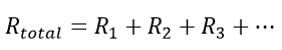
If there are several unbroken layers of different materials forming a wall assembly, the R-value of the entire assembly can be found simply by adding the layers:
With u-factors, it’s not so simple. Since a u-factor is the inverse of an R-value, to find the overall u-factor, we need the following equation:
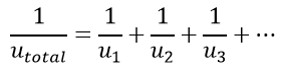
(Which, by the way, is the exact same equation. Since a material’s R-value is the inverse of its u-factor, I’ve just replaced each R-value with the inverse of the u-factor.) Now we can take the inverse of the entire equation to find the overall u-factor:
As I mentioned earlier, this only applies to the part of a wall with unbroken layers, such as the wall cavity. To account for the framing in the wall, a separate u-factor calculation must be done, and then the two u-factors can be combined to get an overall value for a wall assembly with framing (for several examples, read our last article).
If you try to do this using R-value, you will get the wrong answer. R-values of different heat flow pathways through an assembly cannot be added together, averaged or area-weighted to get the overall assembly performance.
This process can be a little confusing, and what the energy codes have tried to do is make it a little bit easier to calculate. For those with the patience to work out an overall wall assembly U-factor, there are tables with U-factor requirements. However, if that seems too time consuming, the energy codes have provided tables listing just a required insulation R-value (and in many cases, an accompanying required continuous insulation R-value).
But how can that be fair or accurate? It’s easy to see that a wall’s overall rating depends on a lot more than just the insulation. What about the air films, cladding, structural sheathing, framing and interior finish? Well, it turns out that the IECC has assumed the following R-values for all of these layers:
- Exterior air film: R-0.17
- Cladding: siding, R-0.62
- Sheathing: 7/16” OSB, R-0.62
- Framing: SPF stud, R-1.25/inch
- Interior finish: ½” drywall, R-0.45
- Interior air film: R-0.68
And guess what? When you use these assumptions to compute the overall U-factor for the prescriptive R-value wall assemblies, they match right up with the U-factor requirements!
As an example, let’s look at the IECC 2015 Residential Code requirements, found in Table R402.1.2 and Table R402.1.4. The U-factor requirement for climate zones 3, 4, and 5 is 0.060 or less. The prescriptive R-value requirement is R-20 (cavity only) or R-13 + 5ci. Below is a table to compute the overall U-factor for the two wall assemblies using the assumptions above and the prescriptive requirements (the complete mathematical rationalization is covered in our last article):
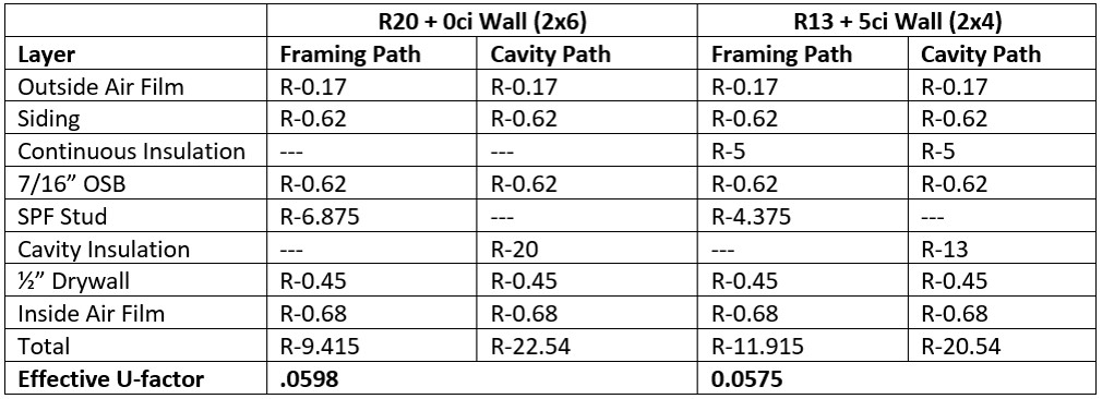
As you can see, the U-factors of these wall assemblies come in just under the 0.060 limit imposed by the u-factor table. This holds true in other climate zones as well. Essentially what we have are two compliance methods that yield the same wall performance.
Finally, you may be wondering why we are given the U-factor method at all, if the two methods are the same and the prescriptive R-value method doesn’t require us to do any math! The answer is flexibility. The energy codes require a certain performance, but acknowledge that there are many ways to get there. One or two ways are listed in the prescriptive R-value tables. But what if a builder wants to use some combination of insulations that are not addressed in the simple R-value insulation options provided in the code? Or, what if the builder wants to use continuous insulation exclusively, and not use any cavity insulation at all? The U-factor method allows this flexibility:
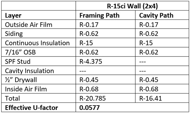
So here we have three equivalent wall assemblies from a thermal performance perspective with very different insulation R-value specifications: R-20 + 0ci, R-13 + 5ci, and R-0 + 15ci. All three satisfy the U-factor requirement in the IECC, though only the first two are mentioned specifically in the prescriptive method table.
It should be clear that there are far more options for a code-compliant wall than the two listed in the prescriptive table. Often, by taking the time to explore some of these other possibilities can lead to higher performance walls, material and labor savings, or both.
If you want to explore some of these options yourself, take a look at this wall calculator developed by the Applied Building Technology Group. This tool checks your wall assembly for code compliance using both the U-factor method and the R-value method. It even evaluates the assembly for moisture control. A version of this calculator for steel-framed walls is currently under development, so stay tuned!