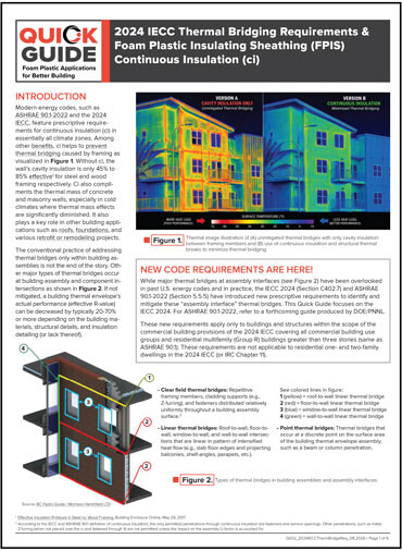
The 2024 International Energy Conservation Code (IECC) introduces new requirements aimed at reducing thermal bridging at critical building envelope interfaces. While continuous insulation (ci) has long been used to improve overall wall performance, the 2024 IECC expands the focus beyond wall assemblies to include the intersections between walls, roofs, floors, balconies, windows, parapets, and structural elements.
Foam Plastic Insulating Sheathing (FPIS) continuous insulation (ci) plays an important role in meeting these new requirements because it helps maintain continuity of the thermal envelope and minimizes unwanted heat flow through highly conductive materials. This Quick Guide explains where the new provisions apply, how compliance can be achieved, and how designers can use FPIS ci and other thermal bridge mitigation strategies to improve building envelope performance.
Key Takeaways
- The 2024 IECC now requires thermal bridge mitigation at key assembly interfaces. Section C402.7 addresses roof-to-wall, floor-to-wall, window-to-wall, parapet, balcony, and structural penetration thermal bridges in commercial and multifamily buildings over three stories.
- Continuous insulation is one of the primary compliance strategies. FPIS ci helps maintain continuity of the thermal envelope and reduces heat loss associated with framing, cladding supports, slab edges, and other conductive building components.
- Multiple compliance pathways are available. Projects may comply through prescriptive requirements, the Total UA (component performance) method, whole-building performance modeling, or approved alternative designs that demonstrate equivalent performance.
Key Definitions
What is thermal bridging?
Thermal bridging occurs when a building component with higher thermal conductivity creates a pathway for heat flow through the building enclosure, reducing overall thermal performance.
What is continuous insulation (ci)?
Continuous insulation is insulation that is continuous across all structural members without thermal bridges other than fasteners and service openings.
Frequently asked questions
What are the thermal bridging requirements in the 2024 IECC?
The 2024 IECC introduces new requirements to address thermal bridging at critical building enclosure interfaces. Section C402.7 requires designers to account for heat flow through assembly transitions and structural elements that can reduce the effective thermal performance of the building envelope. The requirements focus on maintaining continuity of the thermal control layer and mitigating thermal bridges through approved design strategies, thermal breaks, continuous insulation, or performance-based compliance methods.
Which building interfaces must be addressed under IECC Section C402.7?
The code targets building enclosure conditions where significant thermal bridging commonly occurs, including wall-to-floor connections, slab edges, balconies, parapets, roof-to-wall transitions, window-to-wall interfaces, curtain wall connections, cladding support systems, and structural penetrations. These locations often interrupt the insulation layer and can create substantial energy losses if not properly detailed.
How does foam plastic insulating sheathing (FPIS) continuous insulation (ci) help satisfy thermal bridging requirements of the 2024 IECC?
FPIS ci helps create a more continuous thermal barrier by reducing heat flow through framing members, slab edges, cladding attachment systems, and other conductive building components. Because the insulation is installed continuously over the exterior of the structure, it can help maintain thermal continuity across assembly interfaces, improve overall wall performance, and support compliance with the 2024 IECC's thermal bridge mitigation requirements.
Steps
-
Determine applicability.
Verify building type, climate zone, and whether Section C402.7 applies to the project.
-
Identify thermal bridge locations.
Evaluate floor edges, balconies, parapets, window interfaces, cladding supports, and structural penetrations.
-
Incorporate continuous insulation.
Design FPIS ci to provide continuity across assembly interfaces and minimize interruptions in the thermal envelope.
-
Detail critical intersections.
Address slab edges, parapets, window rough openings, and roof-to-wall transitions using code-compliant thermal bridge mitigation strategies.
-
Evaluate attachment systems.
Select cladding support methods, structural thermal breaks, or fastening systems that minimize conductive heat flow.
-
Choose a compliance pathway.
Demonstrate compliance using the prescriptive provisions, Total UA method, whole-building performance modeling, or an approved alternative design.
-
Document compliance.
Include details, calculations, manufacturer data, or modeling results needed to support code compliance.