Designing walls for code-compliant thermal and moisture control is not an intuitive process. Thermal insulation can be installed in the cavity between the studs, as a continuous layer outside the studs, or both. And as we’ve documented in an earlier article, Energy Code Math Lesson: Why an R-25 Wall is Not Equal to a R-20+5ci, comparing the effectiveness of cavity versus continuous insulation is more involved than simply comparing the manufacturer’s R-value.
On the moisture side of things, things get even more complicated. Coordinating the right type of vapor retarder with the location of thermal insulation, air barrier, and water-resistive barrier is difficult to do, especially since the IBC and IRC do not provide a thorough set of guidelines.
One analytical tool that can help you consistently determine code compliance and reliable performance is the freely available wall calculator developed by the Applied Building Technology Group (ABTG). This tool applies the results of an in-depth research report on moisture control also produced by ABTG.
Due to the complexity of the design issues mentioned above, the calculator tool might seem intimidating at first glance. What follows is a quick tutorial to introduce the calculator and its use, and to give a few examples.
The wall calculator page is divided into three distinct areas. The first of these areas contains a description of the calculator’s purpose and brief explanations of the methodologies employed, with links to further resources (figure 1).
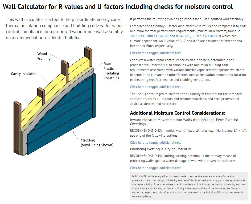
I will leave it as an exercise for you, the reader, to go through this information later, should there be any remaining confusion!
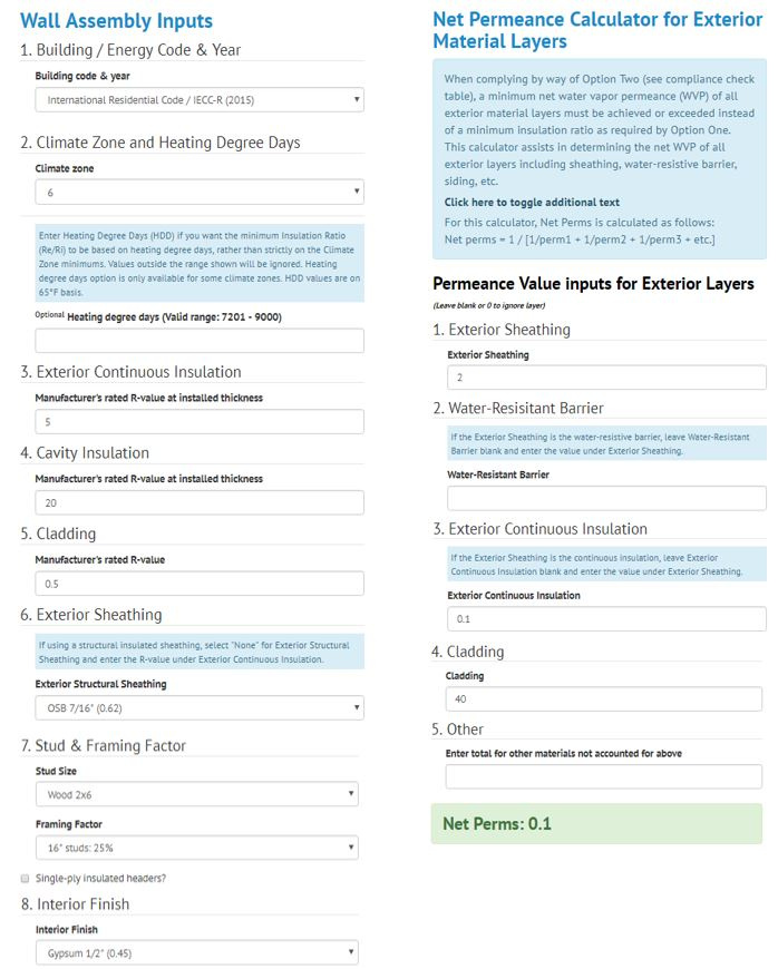
The second area is the input area, below the explanations, and on the left side of the page. Let’s take this area in two parts: the Wall Assembly Inputs, and the Net Permeance Calculator for Exterior Material Layers.
In the Wall Assembly Inputs section (figure 2), the user is asked to select the various components of the wall assembly (tricky, right?). These inputs are then primarily used to determine the thermal behavior and code compliance of the wall.
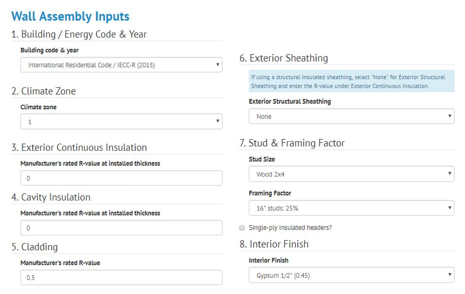
Depending on the type of construction, the applicable building and energy code are selected, followed by the climate zone of the building site. Following this, the user describes the main wall assembly components, including insulation R-values, structural sheathing, framing size and spacing, and interior finish. From these inputs, the calculator is able to compute the assembly effective R-value and U-factor for the wall, and determine whether or not the wall is code compliant in the selected climate zone.
The second section in the input area is concerned primarily with moisture control (figure 3) when following a common “permeance controlled” design approach, whereby the permeance of materials on the interior and exterior of the assembly must be coordinated to ensure that the assembly can dry and that too much water doesn't move into the assembly (i.e., even fast-drying assemblies are problematic if they get wetter than materials can tolerate). Permeance values for many exterior materials can be difficult to find, and may be variable, but are necessary inputs to have any reasonable control over the moisture performance outcome of such wall assemblies. However, providing inputs for this second section is not necessary if using the “temperature controlled” design approach, whereby the specification and location of the insulation with respect to interior vapor retarder options is used as the basis for compliance. In this case, the basic wall assembly inputs are sufficient for the moisture control and U-factor compliance checks.
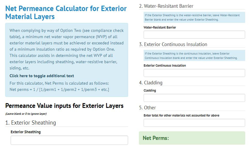
The user is asked to fill in the permeance of any wall assembly components located on the exterior side of the framing. In this section, all the input values are in units of perms. Using these numbers, the calculator determines a net permeance for the exterior layers according the equation listed. Then, this information is combined with the insulation makeup from the previous section, and a determination is made as to what type of vapor retarder ought to be employed.
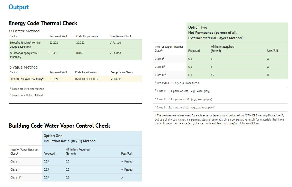
The final area of the calculator is the output, which is located alongside the input sections (figure 4).
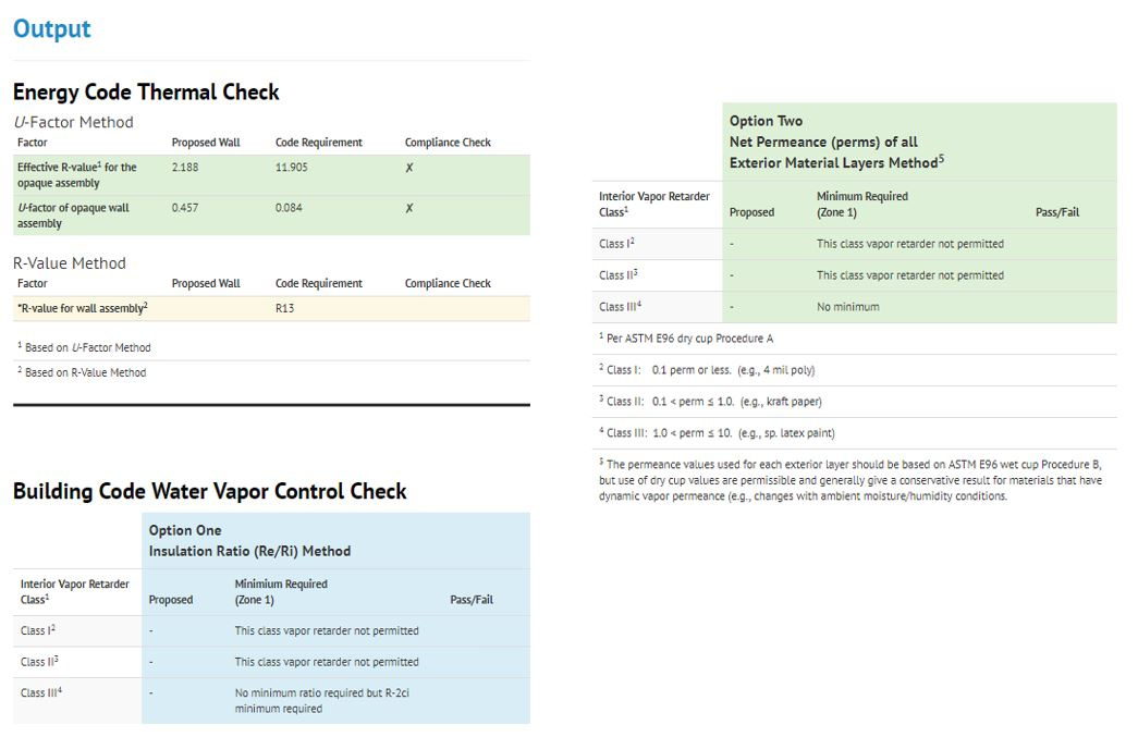
In the output area, there are two checks: the thermal check, and the water vapor control check.
The thermal check displays whether or not the wall passes the thermal performance requirements of the applicable energy code. The codes allow for two methods of compliance: the u-factor method, and the r-value method. That means that if the wall passes the r-value check but not the u-factor check, it is still allowed (and vice-versa). If the wall fails both checks, more insulation must be added. A trial-and-error approach of incrementally adding insulation and checking for compliance can lead to an economic solution, since the calculator updates itself in real time.
The water vapor control check also utilizes two alternate compliance pathways (as mentioned above), in this case to determine the suitability of different classes of vapor retarders for use on the interior of the proposed wall assembly.
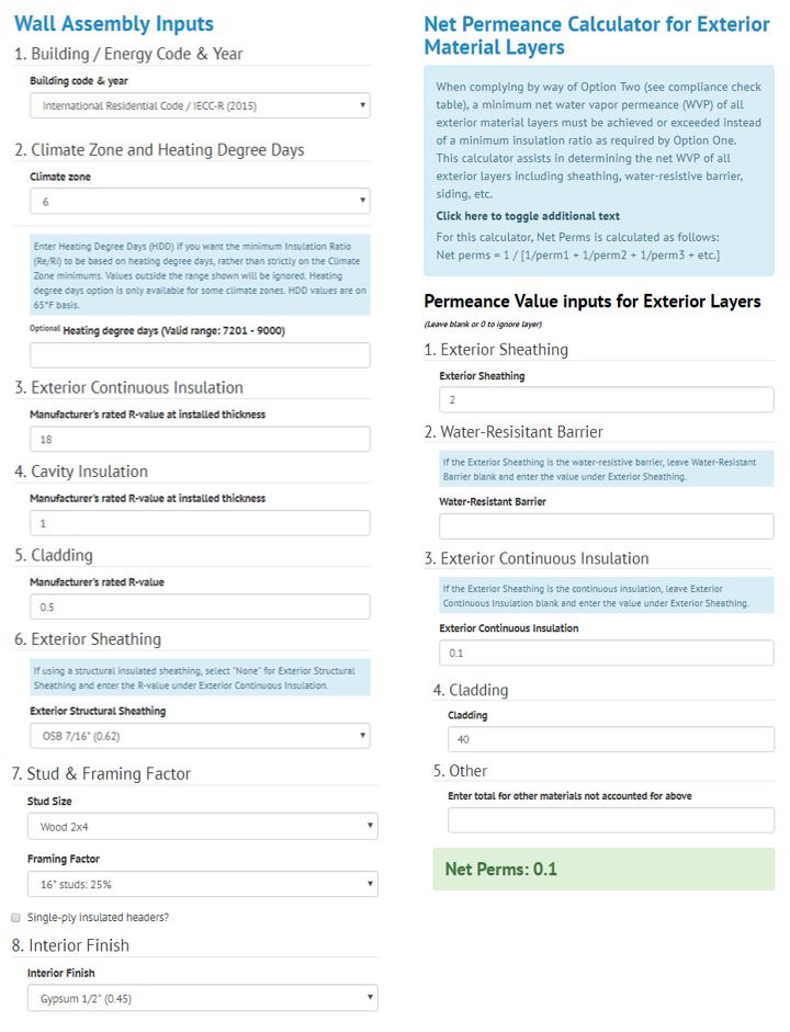
Let’s explore some examples by designing a wall for climate zone 6 using the IRC. First, I will base my input on the “code minimum” for insulation, which is the prescriptive solution of R-20 cavity insulation and R-5 continuous insulation. For the rest of the wall assembly, I will assume R-0.5 for the cladding, 7/16” OSB for structural sheathing, 2x6 studs at 16” o.c., and ½” of drywall on the interior. I will also enter the permeance for these layers, and the input is as appears in figure 5.

For these inputs, we get the output shown in figure 6. To summarize, the thermal check confirms (through both the u-factor analysis and the r-value analysis) that the wall is compliant. The moisture control check allows the use of a class I or class II vapor retarder on the interior surface of the wall according to the insulation ratio method.

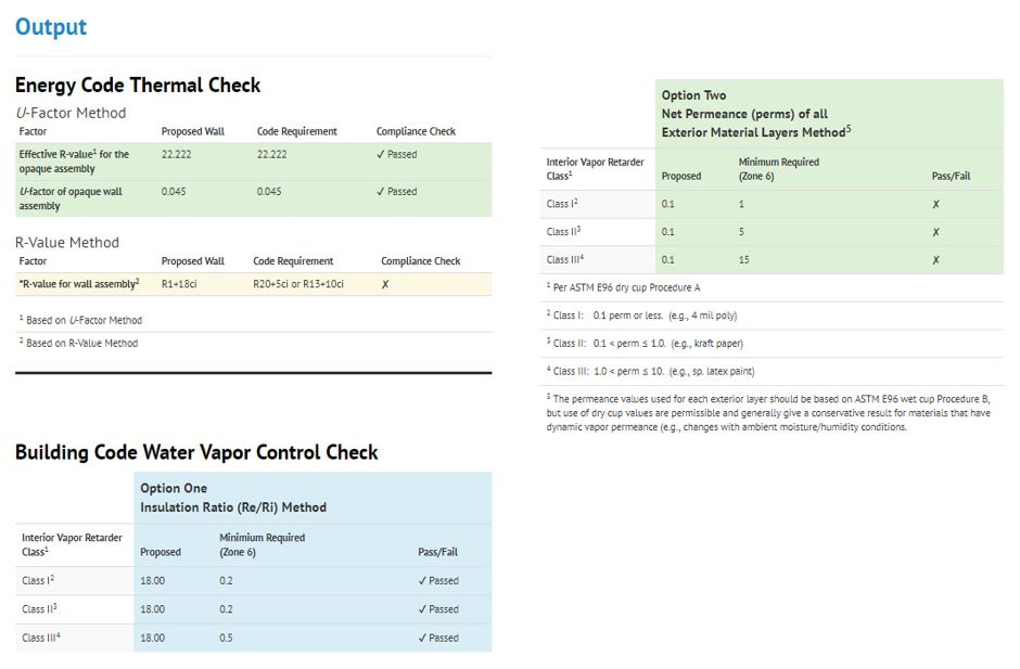
Next, let’s design another wall for climate zone 6, but this time rely entirely on continuous insulation for the thermal performance. Accordingly, I have used trial-and-error to arrive at the minimum amount of continuous insulation that passes the U-factor check, which is R-18. I have used a lower-bound placeholder value of R-1 in the cavity insulation field to roughly account for the R-value of an empty cavity. Inputting a value of zero for cavity insulation will not permit a moisture control check. For the “perfect wall,” the U-factor required for energy code compliance will govern the amount of exterior insulation required. If some amount of cavity insulation is used (still without any interior vapor retarder) the perfect wall becomes a special case of a hybrid assembly. The rest of the input does not vary from before. See the input and output in figures 7 and 8.


Finally, be sure to evaluate the wall design in view of the “Additional Moisture Control Considerations,” which is an important step in completing the a robust, code-compliant design. These considerations may be important to forming an initial trial design, and can be found in the introductory text at the top of the calculator by clicking the toggles to show additional text.
I hope this short guide has been helpful in introducing the uses of the wall calculator tool. I know that unravelling and interpreting the various code provisions can be a difficult task. The wall calculator is designed to do that for you, allowing you to quickly evaluate different design choices, and giving you confidence in your final selection.
For additional information, review the following articles, as well as the previous videos in this series:
Perfect Wall Articles
- Creating the ‘Perfect Wall’: Simplifying Water Vapor Retarder Requirements to Control Moisture
- Perfect Walls are Perfect, and Hybrid Walls Perfectly Good
- Wood Framed Wall Insulation Calculator Explained
- New Wall Design Calculator for Commercial Energy Code Compliance
- Energy Code Math Lesson: Why an R-25 Wall is Not Equal to a R-20+5ci
- Continuous Insulation Solves Energy Code Math Problem
Video Series
- Fear Building Envelopes No More with This Website & Videos
- Video: Thermodynamics Simplified Heat Flows from Warm to Cold
- Video: Moisture Flow Drives Water Induced Problems
- Video: How the 'Perfect Wall' Solves Environmental Diversity
- Video: How Important Is Your WRB?
- Video: A Reliably Perfect Wall Anywhere
- Video: The Best Wall We Know How to Make
- Video: How to Insulate with Steel Studs
- Video: Thermal Bridging and Steel Studs
- Video: Better Residential Energy Performance with Continuous Insulation
- Video: How to (Not) Ruin a Perfectly Good Wall
- Video: Tar Paper and Continuous Insulation? No Problem!
- Video: Do CI and WRBs Go Together?
- Video: Assess Your 'Perfect Wall' Using Control Layers