It’s an easy mistake to make. When a builder comes across an R20 + 5ci insulation requirement, it can be easy to think: R20 + 5ci? Why not just use R-25 in the cavity? Fewer steps, same performance, right?
Wrong.
Don’t worry, energy code math is no different than any other math, and 1+1=2 still holds true. But just like other math, you have to make sure your units agree before you add. Just as 1 apple + 2 oranges doesn’t equal 3 oranges, adding up R-values for insulation which is located in different parts of a wall doesn’t work either.
The reason for this is that cavity insulation is interrupted by framing members, which let heat through more readily, while continuous insulation is uninterrupted, as its name suggests. So a layer of cavity insulation is less effective than a layer of continuous insulation of the same R-value!
Consequently, the real math problem of determining a wall assembly’s overall R-value is not nearly so simple as just adding the nominal R-values of the different insulation components (e.g., R20 + 5ci or R25 + 0ci). The actual procedure laid out in the ASHRAE Handbook of Fundamentals is known as the parallel path method, and we’ll go through it here.
As an example, let’s consider the “R25 + 0ci” and “R20 + 5ci” wall assemblies in the table below. The first step is to determine the R-value for each different “path” that heat can take through the wall. There are two paths: through the framing (studs and headers) and through the cavity. In the table below, the layers for each path and their R-values are listed. The totals are obtained by summing the R-values for each layer in the each path.
| R25 + 0ci Wall | R20 + 5ci Wall | |||
| Layer | Framing Path | Cavity Path | Framing Path | Cavity Path |
| Outside Air Film | R-0.17 | R-0.17 | R-0.17 | R-0.17 |
| Siding | R-0.62 | R-0.62 | R-0.62 | R-0.62 |
| Continuous Insulation | --- | --- | R-5 | R-5 |
| 7/16" OSB | R-0.62 | R-0.62 | R-0.62 | R-0.62 |
| SPF 2x6 Stud | R-6.875 | --- | R-6.875 | --- |
| Cavity Insulation | --- | R-25 | --- | R-20 |
| ½" Drywall | R-0.45 | R-0.45 | R-0.45 | R-0.45 |
| Inside Air Film | R-0.68 | R-0.68 | R-0.68 | R-0.68 |
| Total | R-9.415 | R-27.54 | R-14.415 | R-27.54 |
As you can see, while both walls have the same cavity R-value, the R20 + 5ci wall has a higher R-value for the framing path, thanks to the continuous insulation.
The next step is to combine the two path R-values to get an overall value for the entire wall assembly. To do this, we will assume that the wall assemblies are 25% framing (21% studs and 4% headers) and 75% cavity by area, which is typical for 16” o.c. framing. Then the U-factor for each wall can be obtained with the following formula:
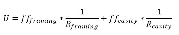
where ff is the framing factor (25% for framing, 75% for cavity). Once the U-factor is found, the assembly R-value is just the inverse of the U-factor. This calculation gives us the following assembly U-factors and R-values:
| R25 + 0ci Wall | R20 + 5ci Wall | |
| Effective U-factor | 0.0538 | 0.0446 |
| Effective R-value | R-18.59 | R-22.43 |
| Qualifying Climate Zones | 3, 4, 5 | 6, 7, 8 |
| Climate Zone Required U-factor | 0.06 | 0.045 |
| Climate Zone Required R-value | R-16.7 | R-22.2 |
Clearly, with complete energy code math, an R25 + 0ci wall (effective R-18.59) is not equivalent to an R20 + 5ci wall (effective R-22.43). Furthermore, it becomes obvious that the R25 + 0ci wall complies with and slightly exceeds the R-value requirements only in Climate Zones 3, 4, and 5 for the International Energy Conservation Code residential provisions. On the other hand, the R20 + 5ci wall complies in all climate zones, including 6, 7, and 8. Where insulation is located on an assembly (cavity vs. continuous) and the amount and size of framing makes a difference.
Now that we’ve covered the math, let’s explore a few more comparisons. For instance, how much insulation would you need in the cavity only to achieve performance equivalent to an R20 +5ci wall? As demonstrated in the table below, a 2x6 wall would need R-38 cavity insulation, and a 2x8 wall would need R-29 cavity insulation. In this second case, less insulation is required in the cavity path since the larger stud depth provides extra heat flow resistance in the framing path.
| R38 + 0ci Wall (2x6) | R29 + 0ci Wall (2x8) | |||
| Layer | Framing Path | Cavity Path | Framing Path | Cavity Path |
| Outside Air Film | R-0.17 | R-0.17 | R-0.17 | R-0.17 |
| Siding | R-0.62 | R-0.62 | R-0.62 | R-0.62 |
| 7/16" OSB | R-0.62 | R-0.62 | R-0.62 | R-0.62 |
| SPF Stud | R-6.875 | --- | R-9.0625 | --- |
| Cavity Insulation | --- | R-38 | --- | R-29 |
| ½" Drywall | R-0.45 | R-0.45 | R-0.45 | R-0.45 |
| Inside Air Film | R-0.68 | R-0.68 | R-0.68 | R-0.68 |
| Total | R-9.415 | R-40.54 | R-11.6025 | R-31.54 |
| Effective U-factor | .0451 | 0.0453 | ||
| Effective R-value | R-22.20 | R-22.06 | ||
Here’s another interesting comparison: an R13 + 5ci wall (effective R-17.39) outperforms an R20 + 0ci wall (effective R-16.71), even though both are considered code compliant in Climate Zones 3, 4, and 5 (see table below). Think about it. The R13 + 5ci wall has R-5 insulation over all of the studs and only R-2 less net insulation at the cavities.
| R20 + 0ci Wall (2x6) | R13 + 5ci Wall (2x4) | |||
| Layer | Framing Path | Cavity Path | Framing Path | Cavity Path |
| Outside Air Film | R-0.17 | R-0.17 | R-0.17 | R-0.17 |
| Siding | R-0.62 | R-0.62 | R-0.62 | R-0.62 |
| Continuous Insulation | --- | --- | R-5 | R-5 |
| 7/16? OSB | R-0.62 | R-0.62 | R-0.62 | R-0.62 |
| SPF Stud | R-6.875 | --- | R-4.375 | --- |
| Cavity Insulation | --- | R-20 | --- | R-13 |
| ½" Drywall | R-0.45 | R-0.45 | R-0.45 | R-0.45 |
| Inside Air Film | R-0.68 | R-0.68 | R-0.68 | R-0.68 |
| Total | R-9.415 | R-22.54 | R-11.915 | R-20.54 |
| Effective U-factor | .0598 | 0.0575 | ||
| Effective R-value | R-16.71 | R-17.39 | ||
The benefits of continuous insulation ought to be clear for timber-framed structures. But for cold-formed steel framing, the impact is even more significant. Steel conducts heat much more efficiently than wood, so the thermal bridging effect is much more pronounced. In these structures, continuous insulation is absolutely necessary for adequate performance. To equate an R20 + 5ci wall to an R25 +0ci wall when building with steel would be a very serious error since the cavity insulation is only about 50% effective in a steel frame wall.
Finally, much more could also be said about how insulation location, types, and relative amounts affect moisture performance for wood and steel frame walls. In general, when done right, placing more insulation on the exterior of an assembly and less in the cavities tends to improve moisture and thermal performance. But we’ve said quite a lot already, so we’ll have to save the details for another time.
For additional information, review the following articles, as well as the previous videos in this series:
Perfect Wall Articles
- Creating the ‘Perfect Wall’: Simplifying Water Vapor Retarder Requirements to Control Moisture
- Perfect Walls are Perfect, and Hybrid Walls Perfectly Good
- Wood Framed Wall Insulation Calculator Explained
- New Wall Design Calculator for Commercial Energy Code Compliance
- Energy Code Math Lesson: Why an R-25 Wall is Not Equal to a R-20+5ci
- Continuous Insulation Solves Energy Code Math Problem
Video Series
- Fear Building Envelopes No More with This Website & Videos
- Video: Thermodynamics Simplified Heat Flows from Warm to Cold
- Video: Moisture Flow Drives Water Induced Problems
- Video: How the 'Perfect Wall' Solves Environmental Diversity
- Video: How Important Is Your WRB?
- Video: A Reliably Perfect Wall Anywhere
- Video: The Best Wall We Know How to Make
- Video: How to Insulate with Steel Studs
- Video: Thermal Bridging and Steel Studs
- Video: Better Residential Energy Performance with Continuous Insulation
- Video: How to (Not) Ruin a Perfectly Good Wall
- Video: Tar Paper and Continuous Insulation? No Problem!
- Video: Do CI and WRBs Go Together?
- Video: Assess Your 'Perfect Wall' Using Control Layers