For an update to this 2017 article, please see the 2020 educational presentation "Applying Recent Building and Energy Code Advancements for Durable and Energy-Efficient Building Enclosures."
If you’ve been around the building industry for a while, you might have heard of the concept of the “perfect wall.” This type of wall locates all of the thermal insulation on the exterior of the structure (see Figure 1). Why is it called the perfect wall? It has several things going for it: it’s conceptually simple, it works in every climate zone, it handles moisture really well by keeping the wall framing warm and drying to the interior such that no interior vapor retarder is required, it works with every type of wall construction (e.g. wood, steel, masonry or concrete) and eliminates the thermal bridging effects inherent in cavity insulation or interior insulation applications. It doesn’t get any better than that, so it deserves the name “perfect.”

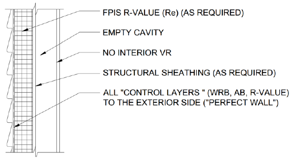
Figure 1. The perfect wall with all insulation to the exterior. The arrangement of control layers on the exterior side depends on what type of exterior insulation is used; the arrangement shown assumes the use of a multi-functional, low-perm exterior insulation like foam plastic foam sheathing that is qualified and installed for use as a water-resistive barrier.
And yet, despite this being the perfect application of cladding, weather-resistant barrier (WRB), foam sheathing, air barriers, studs and so forth, the perfect wall is not necessarily the most practical or preferred solution for every building project. Therefore, it is helpful to have some “good” options that retain the advantages of the perfect wall to varying degrees. Fortunately, a hybrid wall provides a “perfectly” good solution. It offers a builder or designer the versatility to balance performance and practicality according to their specific project and preferences. Thus, the ability to construct a so-called “perfect wall” should not detract from the practicality of pursuing “perfectly” good hybrid wall solutions!
The Hybrid Wall
A hybrid wall is so-named because it relies on a combination of continuous insulation and cavity insulation to get the job done (see Figure 2). This type of wall can be used with a variety of interior vapor retarders depending on climate. The selected vapor retarder, as permitted for a given climate, will also determine how much exterior continuous insulation is required versus cavity insulation to control moisture. This may sound complicated, but it is really simple in concept. It’s also not very difficult to install with the right guidance. Furthermore, these types of hybrid walls can be further enhanced or hybridized with use of a vapor impermeable (closed cell) spray foam insulation. This can be a complete or partial cavity fill, such as a “flash and batt” approach, for the cavity insulation component; but this combination feature will be saved for a later article in Energy Efficiency & Building Science News.

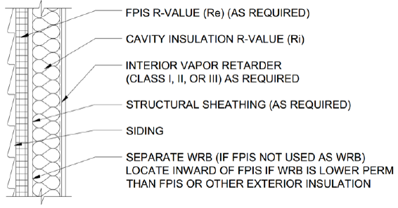
Figure 2. The classic “hybrid wall” assembly with insulation on the exterior and in the cavity.
Simplified Design Guidance
As mentioned, hybrid walls are simple in concept. They also are simple to design and construct using the following step-by-step guidance.
Step 1: The most important thing is to properly specify and locate the key wall components for a given climate zone. These components include the exterior insulation (continuous insulation, “ci”), cavity insulation, and vapor retarder.
But how? Currently, U.S. model codes (e.g., IBC and IRC) only provide cavity insulation and ci guidance for use with Class III vapor retarders, but are silent when a Class I or Class II vapor retarder is used with a hybrid wall (neither disallowing it nor specifying how to do it). Only the Canadian National Building Code provides information for use with Class I and II vapor retarders. By combining these two codes, one gets the complete answer (see Table 1).
Simply follow this table and you are well on your way to designing and build your own hybrid wall (or perfect wall with no interior vapor retarder); pay particular attention to the footnotes.
TABLE 1
CONTINUOUS INSULATION AND VAPOR RETARDER REQUIREMENTS FOR MOISTURE CONTROLa
|
CLIMATE ZONE (Figure X) |
Interior Vapor Retarder Class | |||
| Hybrid Wall Options | "Perfect Wall" | |||
| Class Ib | Class II | Class III | No interior VRc,d | |
| 1-2 | Not Permitted | Not Permitted | Continuous insulation with R-value ≥2 | Continuous insulation with R-value ≥2 |
| 3 | Not Permitted | Continuous insulation with R-value ≥2 | Continuous insulation with R-value ≥2 | |
| 4 | Not Permitted | Continuous insulation with R-value ≥2 | Continuous insulation with R-value ≥2.5 over 2x4 wall. Continuous insulation with R-value ≥3.75 over 2x6 wall | Continuous insulation with R-value ≥4.5 |
| 5 | Continuous insulation with R-value ≥3 over 2x4 wall. Continuous insulation with R-value ≥5 over 2x6 wall | Continuous insulation with R-value ≥5 over 2x4 wall. Continuous insulation with R-value ≥7.5 over 2x6 wall | Continuous insulation with R-value ≥6.5 | |
| 6 | Continuous insulation with R-value ≥7.5 over 2x4 wall. Continuous insulation with R-value ≥11.25 over 2x6 wall | Continuous insulation with R-value ≥8.5 | ||
| 7 | Continuous insulation with R-value ≥5 over 2x4 wall. Continuous insulation with R-value ≥7.5 over 2x6 wall | Continuous insulation with R-value ?10 over 2x4 wall. Continuous insulation with R-value ≥15 over 2x6 wall | Continuous insulation with R-value ≥11.5 | |
| 8 | Continuous insulation with R-value ≥7.5 over 2x4 wall. Continuous insulation with R-value ≥10 over 2x6 wall | Continuous insulation with R-value ≥12.5 over 2x4 wall. Continuous insulation with R-value ≥20 over 2x6 wall | Continuous insulation with R-value ≥14 | |
|
||||

.png)
Figure 3. U.S. Climate Zone Map
For more in-depth information on the analysis behind this table, please see: Assessment of Water Vapor Control Methods for Modern Insulated Light-Frame Wall Assemblies
Additional Important Considerations for All Walls
Step 2: Any wall assembly type (even perfect walls) are made imperfect and unreliable if bulk water management is not properly addressed in a code-compliant manner, considering also best practices to achieve the intent of the code. A code compliant WRB system must be used, and can include various qualified materials including foam sheathing, taped foam sheathing, wraps, spray-applied membranes, etc. For more in-depth information please review: Water Resistive Barrier and its underlying research Water-Resistive Barriers: Assuring Consistent Assembly Water-Penetration Resistance.
Step 3: Installation must include appropriate flashing at penetrations and joint sealing methods to maintain continuity of the WRB with other components such as fenestration. For fenestration in particular, use of pan flashing and rough opening gap air sealing practices are highly recommended as they are important to moisture control. Such bulk water management practices go a long way toward keeping perfect walls perfect and good walls good. For more in-depth information, please review: Residential Window Installation and Commercial Window Installation
Step 4: The wall assembly must include an air-barrier layer for energy efficiency and control of moist air movement into and through assemblies. However, assemblies that have increasing amounts of exterior insulation are less prone to air intrusion related moisture problems (another benefit of the perfect wall and hybrid wall approaches). This same exterior insulation, if qualified and installed as an air-barrier material, can serve this function as well. For more in-depth information, please review: Air Barriers
Step 5: Inward vapor drives must be properly managed when exterior cladding materials provide a “reservoir” for rainwater (e.g., stucco, brick, adhered veneer, etc.). When such claddings absorb rainwater, the sun will cause huge vapor drives into the wall assembly as the cladding dries out. This is known to create moisture accumulation problems within wall assemblies. There are two ways to handle this, and for best effect both should be used: (1) use a vapor retarding (less than 10 perm) layer behind the cladding, many foam sheathing products and some water-resistive barrier products qualify, and/or (2) provide a sufficient ventilation air-gap behind the cladding so as to help mitigate the quantity of inward driven moisture. Use of low perm materials on the exterior must also manage wintertime outward vapor drives using exterior continuous insulation in accordance with Table 1. Consequently, this represents another potential functional advantage of perfect walls and hybrid walls over those that attempt to rely exclusively on high permeance materials on the exterior of a wall to control moisture and drying without considering that this can also increase wetting potential. For more in-depth information, please read: Cladding Attachment through FPIS Research Report, Vinyl Siding Over FPIS Report and NYSERDA Fastening Systems for Continuous Insulation.
Design Resources
Therefore if, for whatever reason, the perfect wall isn’t perfect for your project, the hybrid wall offers a great alternative with many of the same benefits and significant flexibility! We’ve covered good design options and practice at a high level in this article, but there are many resources that go into greater depth if you have further questions. Many of these resources can be found at our best practices page. In addition, a useful “Wall Calculator” design tool has been developed, and is explored in an article entitled Wood Framed Wall Insulation Calculator Explained.
Finally, this article addressed only moisture control considerations for perfect walls and hybrid walls, both of which use exterior continuous insulation. These assemblies must also have insulation material R-values or an assembly U-factor that comply with the energy code. More information on these topics can be found in the following articles: Wall Insulation Code Compliance: R U Confused Yet? and Understanding the Difference Between R-Values and U-Factors.
So get out there and build some good hybrid walls and, if you prefer, give the perfect wall a try!
Recognizing it can sometimes be difficult to locate a specific resource when there is a large volume of content, we’ve curated library pages on the most prevalent subjects of interest as they relate to continuous insulation. These topical library pages pull together the most relevant articles, news items, best practices and other online resources on each topic.
For additional information, review the following articles, as well as the previous videos in this series:
Perfect Wall Articles
- Creating the ‘Perfect Wall’: Simplifying Water Vapor Retarder Requirements to Control Moisture
- Perfect Walls are Perfect, and Hybrid Walls Perfectly Good
- Wood Framed Wall Insulation Calculator Explained
- New Wall Design Calculator for Commercial Energy Code Compliance
- Energy Code Math Lesson: Why an R-25 Wall is Not Equal to a R-20+5ci
- Continuous Insulation Solves Energy Code Math Problem
Video Series
- Fear Building Envelopes No More with This Website & Videos
- Video: Thermodynamics Simplified Heat Flows from Warm to Cold
- Video: Moisture Flow Drives Water Induced Problems
- Video: How the 'Perfect Wall' Solves Environmental Diversity
- Video: How Important Is Your WRB?
- Video: A Reliably Perfect Wall Anywhere
- Video: The Best Wall We Know How to Make
- Video: How to Insulate with Steel Studs
- Video: Thermal Bridging and Steel Studs
- Video: Better Residential Energy Performance with Continuous Insulation
- Video: How to (Not) Ruin a Perfectly Good Wall
- Video: Tar Paper and Continuous Insulation? No Problem!
- Video: Do CI and WRBs Go Together?
- Video: Assess Your 'Perfect Wall' Using Control Layers