When one comes across the R 13 + 7.5 ci wall insulation requirement in the International Energy Conservation Code (IECC) commercial provisions, it can be tempting to just add the two R-values and install R-20.5 rated insulation in the cavity with the assumption being that the same performance can be achieved with fewer steps. However, by employing just R-20.5 cavity insulation, one would be accepting a 16 percent decrease in thermal performance in a wood-framed wall, or a 40 percent decrease in a steel stud wall, when compared to the energy code requirement.
Continuous insulation (ci) and cavity insulation products are both sold with R-value ratings, but the way these two products are used in wall construction means they do not have the same effectiveness. (The article assumes design according to U.S. energy codes. However, the concepts presented here are applicable in all territories, as the underlying science does not change.) Cavity insulation is interrupted by framing members, which let heat through the insulation layer. On the other hand, ci, as the name suggests, is uninterrupted (except at fasteners and service openings, as defined by IECC). So a layer of cavity insulation is less effective than a layer of ci of the same R-value.
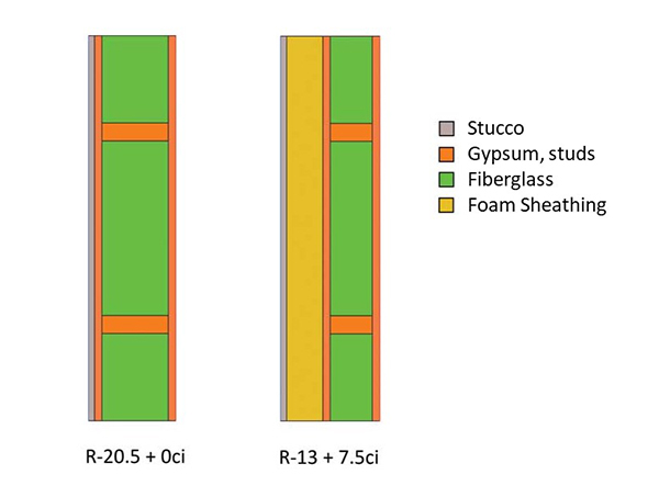
Figure 1: A cross-section of two walls. On the left is the R-20.5 + 0 continuous insulation (ci) wall, and the R-13 + 7.5 ci wall is on the right.
This can easily be seen with thermal modeling software. Figure 1 shows a cross-section of two walls. The left wall is the R-20.5 + 0 ci, and the right is R-13 + 7.5 ci. When these two are subjected to a temperature differential—such as winter outside and room temperature inside—heat flows through the wall from the warm to the cold side. Figure 2 shows the temperature flux, or rate of change, through these walls. As one can see, there is high flux through the wall studs. In the wall without ci, the studs act like a ‘heat highway,’ allowing heat an easy route around the cavity insulation—out of the wall in cold climates and into the wall in hot regions. When ci is added, the highway ends, and heat is forced to slowly seep through the last layer of insulation.
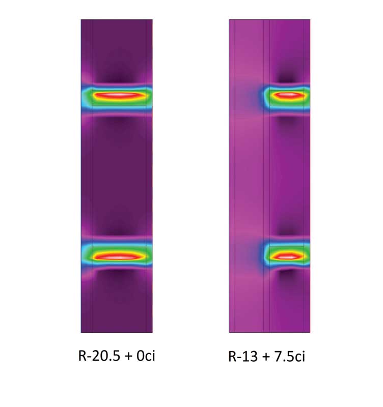
Figure 2: Thermal modeling reveals there is high temperature flux through the wall studs.
The real math problem of determining a wall assembly’s overall R-value is not nearly so simple as just adding the nominal R-values of the different insulation components (e.g. R 13 + 7.5 ci = R 20.5). Depending on whether wood or steel framing is being employed, different procedures for calculating the assembly R-value of a wall are laid out in the American Society of Heating, Refrigerating and Air-conditioning Engineers’ (ASHRAE’s) 2017 ASHRAE Handbook–Fundamentals and IECC. This article will discuss both the methods. But first, let us look at some of the terms.
R-values and U-factors
In this article, the u-factor (or C-factor) of a component or an assembly refers to its thermal conductance. A u-factor is given in units as W/m2.K (Btu/h-F-sf). One way of understanding these units is the rate of heat transfer (W) through a material with a given u-factor is proportional to the temperature difference on both sides of the material (K) and the surface area available (m2).
The R-value of a component or assembly is the inverse of its u-factor. The R-value describes an object’s thermal resistivity, and the units for R-value are simply the inverse of the u-factor: K.m2/W (sf-F-h/Btu). Therefore, good conductors have low R-values and high u-factors, and good insulators have high R-values and low u-factors. If one knows the R-value of a layer or an assembly, one can find its u-factor by simply calculating the inverse. R-value and u-factor requirements mentioned in this article are taken from IECC.
While any layer of material can be described by its R-value, U.S. energy codes only refer to the R-values of insulation layers in the prescriptive R-value compliance path. Conversely, while any layer or assembly also has a u-factor, energy codes only discuss the u-factors of entire wall assemblies. When this is done, a capital ‘U’ is used. For the remainder of this article, a capital ‘U’ will be employed when discussing assembly U-factors.
If an R-value and a u-factor are just two sides of the same coin, why would the energy codes include both as separate compliance paths? This is because the R-values of individual components like cavity insulation and ci can be easier to work with and understand than assembly U-factors. Many people can picture an R-13 insulation batt whereas a wall assembly with a U-factor of 0.064 is not an intuitive notion. One must delve into some math to understand what this means.
If there are several unbroken layers of different materials forming a wall assembly, the R-value of the entire assembly can be found simply by adding the layers:
Rtotal=R1+R2+R3+…
With u-factors, it is not so simple. Since a u-factor is the inverse of an R-value, to find the overall u-factor, one needs the following equation:
1/utotal =1/u1 +1/u2 +1/u3 +…
(Which, by the way, is the exact same equation. Since a material’s R-value is just the inverse of its u-factor, the author just replaced each R-value with the inverse of the u-factor.) Now one can take the inverse of the entire equation to find the overall u-factor:
utotal=1/(1/u1 +1/u2 +1/u3 +…)
As mentioned earlier, this only applies to the part of a wall with unbroken layers, such as the wall cavity. To account for the framing in the wall, a separate u-factor calculation must be done, and then the two u-factors can be combined to get an overall value for the entire assembly. If one tries to do this using R-values, the answer will be wrong. R-values of different heat flow pathways through an assembly cannot be added together, averaged, or area-weighted to get the overall assembly performance.
Energy codes have tried to make compliance possible without doing any math because the math is not intuitive. This is why they have provided tables listing just a required insulation R-value (and in many cases, an accompanying required ci R-value).
How can this be fair or accurate? It is easy to see a wall’s overall rating depends on a lot more than just the insulation. What about the air films, cladding, structural sheathing, framing, and interior finish? Well, it turns out IECC has assumed the following R-values for all of these layers in a wall in commercial construction:
- exterior air film: R-0.17;
- cladding: stucco, R-0.08;
- sheathing: 16 mm (5/8 in.) gypsum, R-0.56;
- interior finish: 16 mm gypsum, R-0.56; and
- interior air film: R-0.68.
When one uses these assumptions to compute the overall U-factor for the prescriptive R-value wall assemblies, they match right up with the U-factor requirements. To see this correspondence in action, one needs to go through the approved U-factor calculation procedures.
Good energy code math
For wood walls, the “parallel path” method is appropriate, (see for example, the “R 20.5 + 0 ci” and “R 13 + 7.5” wall assemblies in Figure 1). This method of calculation can be applied to any combination of ci and cavity insulation required for wood-framed construction (whether commercial or residential). The first step is to determine the R-value for each “path” heat can take through the wall. There are two paths—through the framing (studs and headers) and cavity. In Figure 3, the layers for each path and their R-values are listed. The totals are obtained by summing the R-values for each layer in each path.
| R20.5 + 0ci Wall (2x6) | R13 + 7.5ci Wall (2x4) | |||
| Layer | Framing Path | Cavity Path | Framing Path | Cavity Path |
| Outside Air Film | R-0.17 | R-0.17 | R-0.17 | R-0.17 |
| Stucco | R-0.08 | R-0.08 | R-0.08 | R-0.08 |
| CI | --- | --- | R-7.5 | R-7.5 |
| 16 mm (5/8 in.) Gypsum | R-0.56 | R-0.56 | R-0.56 | R-0.56 |
| SPF Stud | R-6.875 | --- | R-4.375 | --- |
| Cavity Insulation | --- | R-20.5 | --- | R-13 |
| 16 mm (5/8 in.) Gypsum | R-0.56 | R-0.56 | R-0.56 | R-0.56 |
| Inside Air Film | R-0.68 | R-0.68 | R-0.68 | R-0.68 |
| Total | R-8.925 | R-22.55 | R-13.925 | R-22.55 |
Table 1: A list of the layers for each path heat can take through the walls and their R-values.
One can see while both walls have the same cavity path R-value, the R 13 + 7.5 ci wall has a higher R-value for the framing path (even with a smaller thermal contribution from the thinner 2 x 4 wall framing), thanks to the ci.
The next step is to combine the R-values of the two paths to get an overall value for the entire wall assembly. To do this, the author assumes the wall assemblies are 25 percent framing (21 percent studs and 4 percent headers) and 75 percent cavity by area, which is typical for 406 mm (16 in.) o.c. framing. Then the U-factor for each wall can be obtained with the following formula:
U=ffframing*1/Rframing +ffcavity*1/Rcavity
where ff is the framing factor (25 percent for framing and 75 percent for cavity). Once the U-factor is found, the assembly R-value is just the inverse of the U-factor. This calculation gives us the assembly U-factors and R-values found in
Figure 4.
| R20.5 + 0ci Wall | R13 + 7.5ci Wall | |
| Effective U-factor | 0.061 | 0.051 |
| Effective R-value | R-16.393 | R-19.608 |
| Qualifying Climate Zones | 5 | 6, 7 |
| Climate Zone Required Effective U-factor | 0.064 | 0.051 |
| Climate Zone Required Effective R-value | R-15.625 | R-19.608 |
Table 2: The U-factors and R-values for the wall assemblies.
Clearly, with complete energy code math, an R 20.5 + 0 ci wall (effective R-16.393) is not equivalent to an R 13 + 7.5 ci wall (effective R-19.608). Further, it becomes obvious the R 20.5 + 0 ci wall complies with and slightly exceeds the R-value requirements only in climate zone five for IECC residential provisions. On the other hand, the R 13 + 7.5 ci wall complies in climate zones up to seven according to the commercial provisions of the IECC. It is easy to see the location of the insulation makes a big difference (cavity vs. continuous).
Since the math is covered, let us explore a few more comparisons. For instance, how much cavity insulation would one need to achieve performance equivalent to an R 13 + 7.5 ci wall? As demonstrated in Figure 5, R-24 cavity insulation would be required. In most cases, this would require using 2 x 8 studs, since cavity insulation greater than R-21 is generally thicker than the cavity in a 2 x 6 wall. By using ci, the wall is kept to half the thickness it would be otherwise, saving lots of valuable interior floor space.
| R24 + 0ci Wall | ||
| Layer | Framing Path | Cavity Path |
| Outside Air Film | R-0.17 | R-0.17 |
| Siding | R-0.08 | R-0.08 |
| 16 mm (5/8 in.) Gypsum | R-0.56 | R-0.56 |
| SPF 2x8 Stud | R-9.0625 | --- |
| Cavity Insulation | --- | R-24 |
| 16 mm (5/8 in.) Gypsum | R-0.56 | R-0.56 |
| Inside Air Film | R-0.68 | R-0.68 |
| Total | R-11.1125 | R-26.05 |
| Effective U-factor | 0.051 | |
| Effective R-value | R-19.608 | |
Table 3: An R-24 cavity insulation would be needed to achieve performance equivalent to an R13 + 7.5 ci wall.
The benefits of ci ought to be clear for timber-framed structures, but for cold-formed steel framing, the impact is even more significant. Steel conducts heat more efficiently than wood, so the thermal bridging effect is much more pronounced. In this type of structure, ci is absolutely necessary for adequate performance. The calculation method provided in IECC for commercial steel-framed walls is arguably simpler to implement than the parallel path method for wood walls.
Essentially, the code treats the cavity/stud layer of the wall assembly as a single layer with its own R-value, and provides a correction factor to compute the appropriate R-value. For example, in climate zone six, IECC commercial provisions require a wall u-factor of 0.064 or less. The correction factor for climate zone six with steel studs at 406 mm (16 in.) o.c. is 0.46. Another way of saying this is a layer of cavity insulation contributes only 46 percent of the listed R-value to the overall wall performance. Consider the two qualifying walls in Figure 6. The advantage of ci over cavity insulation is more obvious in steel-framed walls. In this comparison, adding just R-2.5 of ci more than makes up for removing cavity insulation worth R-5. With deeper 152- and 203-mm (6- and 8-in.) steel studs, the disparity only grows. The full list of correction factors is shown in Figure 7.
| Layer | R13 + 7.5ci Wall | R8 + 10ci Wall |
| Outside Air Film | R-0.17 | R-0.17 |
| CI | R-7.5 | R-10 |
| Stucco | R-0.08 | R-0.08 |
| 16 mm (5/8 in.) Gypsum | R-0.56 | R-0.56 |
| Correct Cavity Insulation | R-13x0.46=R-5.98 | R-8x0.46=R-3.68 |
| 16 mm (5/8 in.) Gypsum | R-0.56 | R-0.56 |
| Inside Air Film | R-0.68 | R-0.68 |
| Assembly R-value (sum) | R-15.53 | R-15.73 |
| Assembly U-factor | 0.064 | R-0.064 |
Table 4: The advantage of ci over cavity insulation is more obvious in steel-framed walls. Adding just R-2.5 of ci more than makes up for removing cavity insulation worth R-5.
| OC Stud Spacing | ||||
| 406 mm (16 in.) | 610 mm (24 in.) | |||
| Stud Depth | Cavity Insulation | Correction Factor | Cavity Insulation | Correction Factor |
| 89 mm (3.5 in.) | R-13 | 0.46 | R-13 | 0.55 |
| R-15 | 0.43 | R-15 | 0.52 | |
| 152 mm (6 in.) | R-19 | 0.37 | R-19 | 0.45 |
| R-21 | 0.35 | R-21 | 0.43 | |
| 203 mm (8 in.) | R-25 | 0.31 | R-25 | 0.38 |
Table 5: A list of correction factors.
If one would like to further explore proper wall design for thermal behavior, visit the Wood Frame Wall Calculator developed by the Applied Building Technology Group. (Visit www.appliedbuildingtech.com/fsc/calculator for the wall calculator.) This tool uses the approach the authors have outlined to compute the effective R-value and U-factor of a wood-framed wall, and depending on climate zone, determines whether the wall is code-compliant. Additionally, the calculator handles moisture code compliance, another tricky area in design. (A Steel Frame Wall Calculator is also available.)
Timothy Ahrenholz is a special projects engineer with the Applied Building Technology Group. In this role, he develops design solutions for foam sheathing products. Ahrenholz has been involved with standards development and code change proposals for the I-codes and the National Building Code of Canada (NBC). He holds a master’s degree in civil engineering with a structural focus from the University of Illinois, and bachelor’s degrees in physics and mathematics from Covenant College. He can be reached at tahrenholz@qualtim.com.
For additional information, review the following articles, as well as the previous videos in this series:
Perfect Wall Articles
- Creating the ‘Perfect Wall’: Simplifying Water Vapor Retarder Requirements to Control Moisture
- Perfect Walls are Perfect, and Hybrid Walls Perfectly Good
- Wood Framed Wall Insulation Calculator Explained
- New Wall Design Calculator for Commercial Energy Code Compliance
- Energy Code Math Lesson: Why an R-25 Wall is Not Equal to a R-20+5ci
- Continuous Insulation Solves Energy Code Math Problem
Video Series
- Fear Building Envelopes No More with This Website & Videos
- Video: Thermodynamics Simplified Heat Flows from Warm to Cold
- Video: Moisture Flow Drives Water Induced Problems
- Video: How the 'Perfect Wall' Solves Environmental Diversity
- Video: How Important Is Your WRB?
- Video: A Reliably Perfect Wall Anywhere
- Video: The Best Wall We Know How to Make
- Video: How to Insulate with Steel Studs
- Video: Thermal Bridging and Steel Studs
- Video: Better Residential Energy Performance with Continuous Insulation
- Video: How to (Not) Ruin a Perfectly Good Wall
- Video: Tar Paper and Continuous Insulation? No Problem!
- Video: Do CI and WRBs Go Together?
- Video: Assess Your 'Perfect Wall' Using Control Layers